
Creating a Test Plan - FCC Booster
The FCC Booster option is used for FCC / IC (ISED) certification testing of signal boosters (FCC Part 20). The test path involves a signal generator (VSG), the EUT and a spectrum analyzer (SA): the VSG feeds the signal and the output through the booster is measured.
CMRS
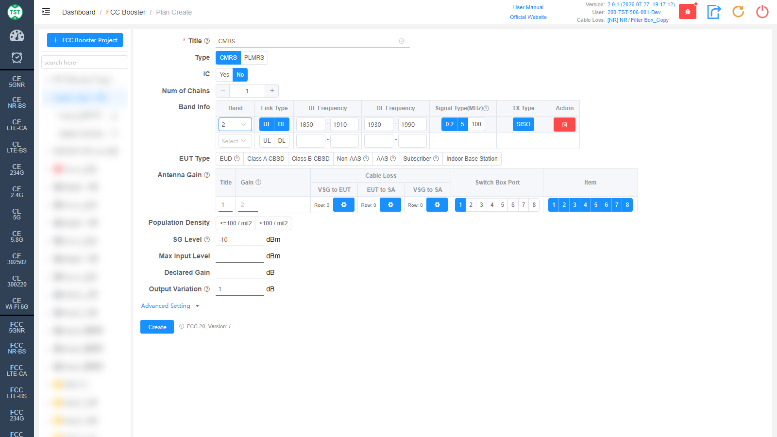
Title: Test plan name, entered by the user.
Type: Booster category:
CMRS: Commercial Mobile Radio Service (cellular band) booster.
PLMRS: Private Land Mobile Radio Service booster.
IC: Whether to test according to Canadian IC (ISED) requirements as well, default No.
Num of Chains: Number of transmit chains.
Band Info: Operating bands supported by the product, one band per row:
Band: Band number, e.g., Band 2 / 5. Frequencies are filled in automatically after selection.
Link Type: Link direction, multi-select UL / DL.
UL Frequency / DL Frequency: Uplink / downlink frequency ranges (MHz), auto-filled and editable.
Signal Type(MHz): Test signal types, multi-select: 0.2 (GMSK 0.2 MHz, narrowband) / 5 (AWGN 5 MHz, broadband) / 100 (AWGN 100 MHz, broadband).
TX Type: Transmission type SISO.
Action: Delete a band row; add a new row via the bottom Select drop-down.
EUT Type: Type of the equipment under test:
EUD: End User Device.
Class A CBSD / Class B CBSD: Class A / B Citizens Broadband Radio Service Device.
Non-AAS: Non-AAS fixed station and base station.
AAS: AAS fixed station and base station.
Subscriber: Subscriber equipment.
Indoor Base Station: Indoor base station.
Antenna Gain: Antenna gain and cable loss configuration:
Title / Gain: Antenna number and gain (dBi).
Cable Loss - VSG to EUT: Cable loss from the signal generator to the EUT.
Cable Loss - EUT to SA: Cable loss from the EUT to the spectrum analyzer.
Cable Loss - VSG to SA: Cable loss of the direct VSG-to-SA path (for calibration). How to Create Common Cable Loss.
Switch Box Port: Port number of the switch connected to the antenna.
Item: Test items per antenna; the numbers correspond to:
(F2001) Out of band rejection
(F2002) AGC threshold
(F2003) Input-versus-output signal comparison
(F2004) Input/output power and amplifier/booster gain
(F2005) Out-of-band/out-of-block (including intermodulation) emissions
(F2006) Spurious emissions
(F2007) Frequency stability measurements
(F2008) Adjacent Channel Leakage Power
Population Density: Population density of the usage area: <=100 / mil² / >100 / mil². Affects the applicable limits.
SG Level: Signal generator level (dBm), default -10. For the out of band rejection test: a sufficient level to affirm that the out-of-band rejection is > 20 dB above the noise floor and will not engage the AGC during the entire sweep.
Max Input Level: Maximum input level (dBm).
Declared Gain: Gain declared by the manufacturer (dB).
Output Variation: Output variation (dB), default 1. For the AGC test: increase the input level until a 1 dB increase in the input signal power no longer causes a 1 dB increase in the output signal power.
PLMRS
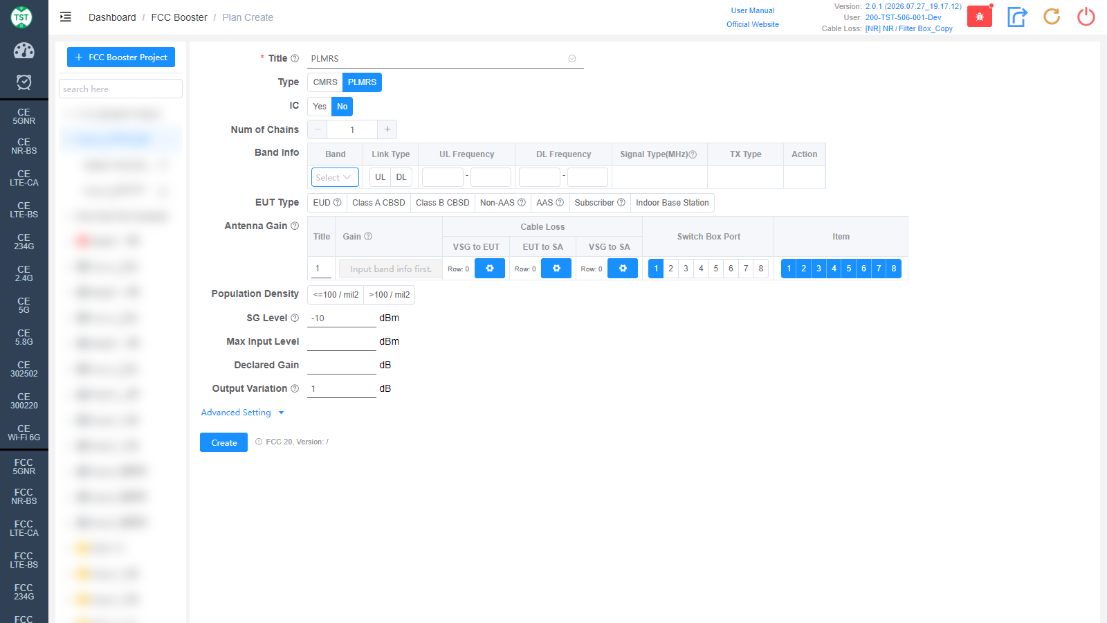
The PLMRS form has the same structure as CMRS; fill in the bands according to the private land mobile radio bands actually supported by the product.
Advanced Setting
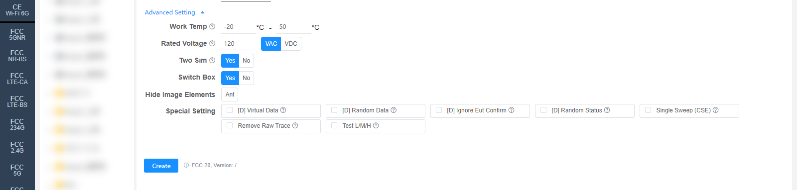
All settings in Advanced Setting can generally be kept at their default values. Adjust them only when the test results are abnormal or there are special test requirements.
Work Temp: Normal operating temperature range (°C). Affects the frequency stability test.
Rated Voltage: Rated operating voltage (VAC / VDC). Affects the frequency stability test.
Two Sim: Whether to accommodate two simultaneous signals within the passband, default Yes.
Switch Box: Whether to use a Switch Box (RF switch).
Hide Image Elements: Elements to hide in report images (e.g., the Ant marker).
Special Setting: Special settings. Options prefixed with [D] are debug options:
[D] Virtual Data / [D] Random Data / [D] Ignore Eut Confirm / [D] Random Status: Debug options.
Single Sweep (CSE): CSE uses single sweep. Requires a retest to take effect (ReTest).
Remove Raw Trace: Remove the raw trace and hide RBW/VBW in the report.
Test L/M/H: Test BW and power on LCH / MCH / HCH (for F2003 / F2004).
Corresponding software option: FCC 20 (FCC Part 20)